|
|
|
Differences between ESD and EOS |
Both ESD (Electro Static Discharge) and EOS (Electrical
Over Stress) are related types of voltage overstress. The
clear difference is that ESD is a very high voltage (>500V)
with relatively short duration (<1μsec) whereas EOS is
a moderate voltage (<100V) with longer time span (normally>1μsec).
Richtek IC ESD cells are designed to survive the energy
of an ESD pulse based on Human Body Model (HBM) or CDM (Charged
Device Model), which are well quantified and represent a
certain energy surge in the ESD cell. EOS events are longer
duration events, and the energy surge during EOS can easily
exceed the levels of ESD events.
.png) |
|
Measuring ESD cell characteristics |
|
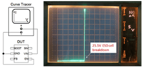
To see the point where IC failure starts to happen, you
can measure the actual ESD breakdown voltage, either via
a curve tracer or by applying a pulsed current to the device
under test, which is a more precise measurement
to check the actual ESD cell failure point. The ESD cell
maximum surge energy can be calculated from these measurements.
|
|
 |
 |
|
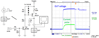
The Buck converter
RT7285C VIN ESD cell breakdown lies around 25.5V, and
rises sharply without snap-back. |
A simple switched current source with adjustable current
and pulse width can show the ESD cell breakdown and by increasing
the current the failure point can be captured. |
|
|
|
Common reasons for VIN EOS: Supply hot-plug |
 |
|
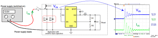
One of the most common reasons for power IC VIN EOS is power supply hot-plug
events. Appliances that run from wall adapters with DC jacks should
always consider hot-plug events. In the lab it is easy to duplicate
the hot plug event by connecting live power supply leads to an application
which has low ESR ceramic input capacitors. The amplitude of the
voltage spike depends on several parameters like cable wire type
and length, supply impedance, input capacitor ESR and the MLCC DC
bias effect. |
|
There are several ways to reduce the voltage ringing amplitude during
hot-plug : You can increase the output impedance of the switch-mode adapter input supply, you can increase the adapter cable resistance
or improve the coupling between positive and negative wires. Another
solution is to add an RC snubber at the converter input. For more
details on these solutions
|
|
DIY tools for generating EOS |
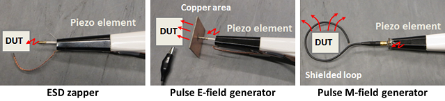 |
|
Read here how to build these handy tools for stress testing your design on EOS. |
Breakdown characteristics of different ESD cell types
Other causes for power IC VIN EOS and their solutions |
For more details, please download the full application note
“Analysing
VIN Overstress in Power ICs” |
|
Feature Product |
|
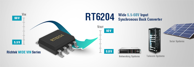
RT6204 - Richtek’s latest addition to the wide VIN converter range |
 |
 |
RT6204 is a Synchronous Buck converter
with a wide input range of 5.5V to 60V and
an output range adjustable from 0.8V to 50V
with 500mA current capability.
It
switches at 350kHz and is housed in a
SOP-8 thermally effective package.
The wide input range in combination with high step down
capability makes it suitable for virtually any industrial
application range, from battery fed automotive to 12V/24V/48V industrial
supplies. |
|
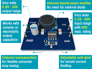
Featuring PSM mode for enhanced light load efficiency, RT6204 uses
current mode topology with external compensation, allowing great
flexibility in loop tuning using either ceramic or electrolytic
output capacitors. The 80V max rating makes this IC very tolerant
to hot-swapping and other supply voltage transients. Slew rate limited
switching helps to reduce EMI radiation.
Applications: automotive
electronics, solar power systems, networking and telecommunication
systems, industrial and communication low power systems, LCD monitors
and TVs, LED lighting, motor drive bias supply, etc.
Please contact our sales offices for samples to get your design started in no time. |
|
New Products |
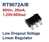 |
RT9072A/B is a wide 4.5V to 80V
input, wide 1.25V to 60V output, 20mA Low dropout voltage
Linear Regulator in SOT-23-5 package. -80V reverse-battery
protection, ±3% output tolerance over line, load &
temperature range and low quiescent current make it a robust
solution for powering sensors or MCUs in battery-powered
applications, telecom and Datacom, automotive applications,
etc. |
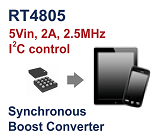 |
RT4805 is 1.8V to 5V input, 2.85V to 4.4V
output, up to 2A, 2.5MHz, synchronous Boost converters with
Bypass Mode in WL-CSP-16B 1.67x1.67 package in
I2C
controlled interface. Built-in power transistors, ultra-low
operating quiescent current and smooth transitions between
bypass mode and boost mode or forced low Iq bypass mode
makes it suitable for battery powered wearables,
sensors, smartphones and tablets, 2.5G/3G/4G mini-module
data cards. |
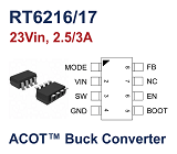 |
RT6216 /
RT6217 ACOT® Synchronous Buck Converters family
are 4.5V to 23V input, 2.5A/3A
output current, 500kHz or 800kHz for options, in compact
TSOT-23-8 packages. The ACOT topology provides
ultra-fast transient response, and a constant switching
frequency, ideal for Set Top Box, portable TV, access point
router, DSL modern and LCD TV powered from 5V, 12V or 19V
supplies.
Also see other ACOT® products |
|
| |
|